LED Lighting for the Super Duper Joy Stick
The images in this gallery are 1400px and are best viewed on a PC or laptop, although you can view scaled-down images on phones, and tablets.
I hope you enjoy viewing these images as much as I enjoyed taking them.
Gallery
For my Winter Build Challenge project for 2019, I decided to use a LED lighting system I purchased from Lake Microsystems. I consulted SFRCF club member Paul Fleming and he invited me to his shop to vacuum form some lenses for the wing tip navigation lights. I traveled to Paul's shop with Dick Robb, who has experience with the process and is also a club member.
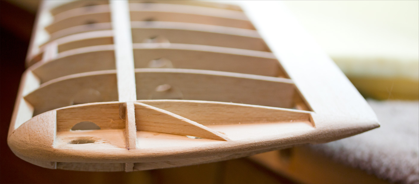
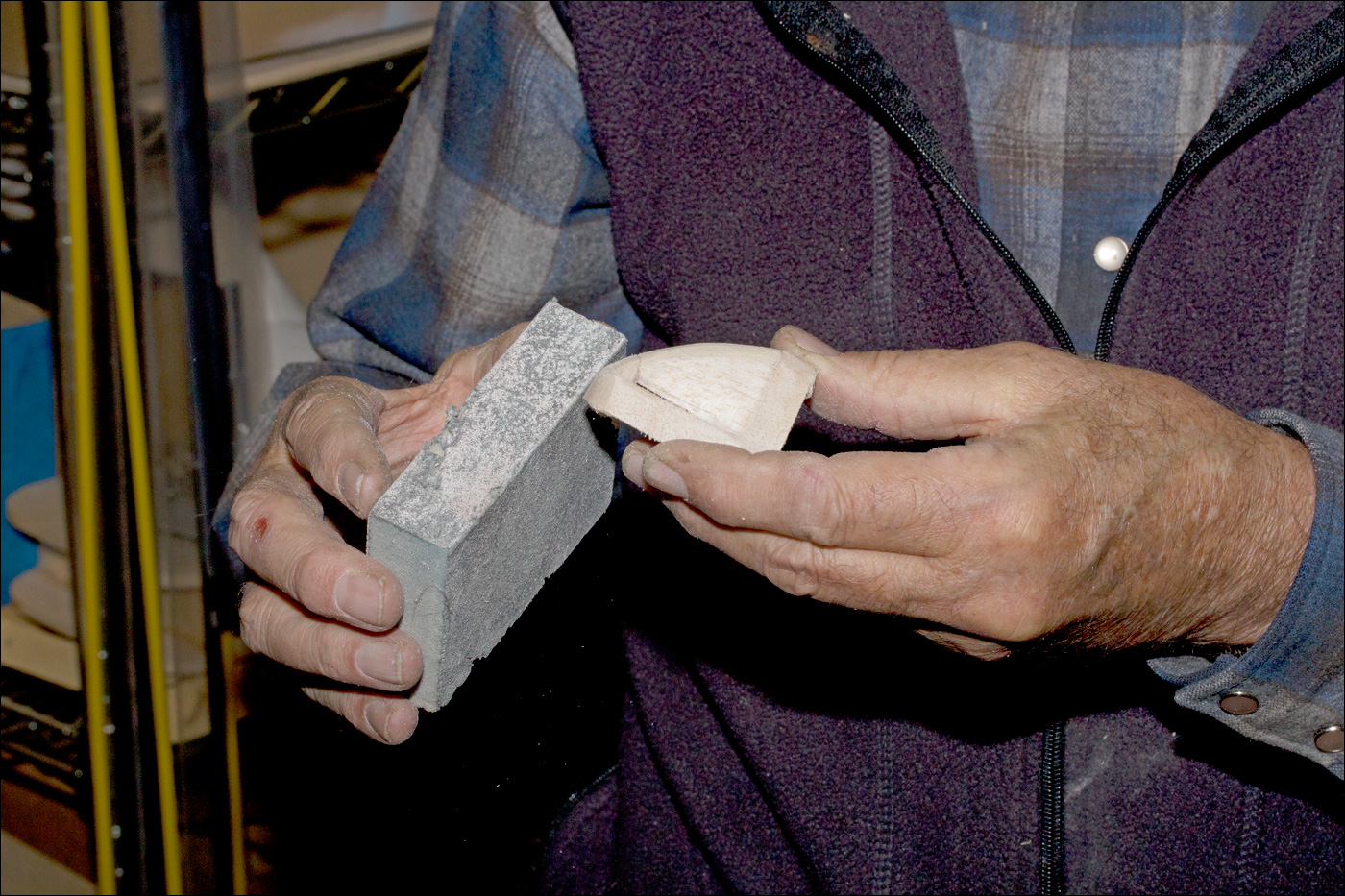
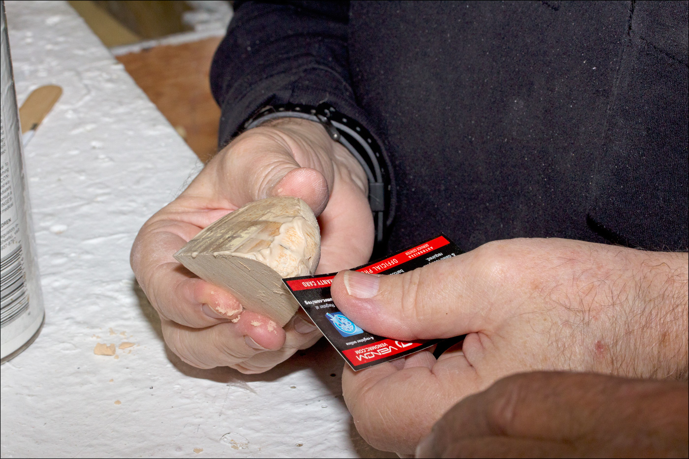
The first part of the process was to cut out part of the wing-tip in order to create a mold for the lenses. While Dick sanded the "notch," Paul added an additional layer of balsa to the bottom and back of the cut-out balsa in order to increase the size of the mold.

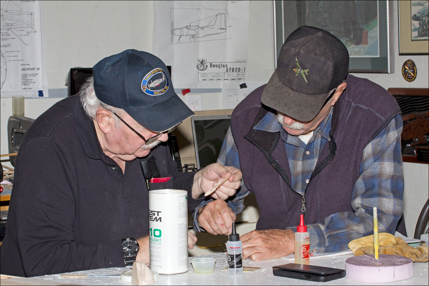
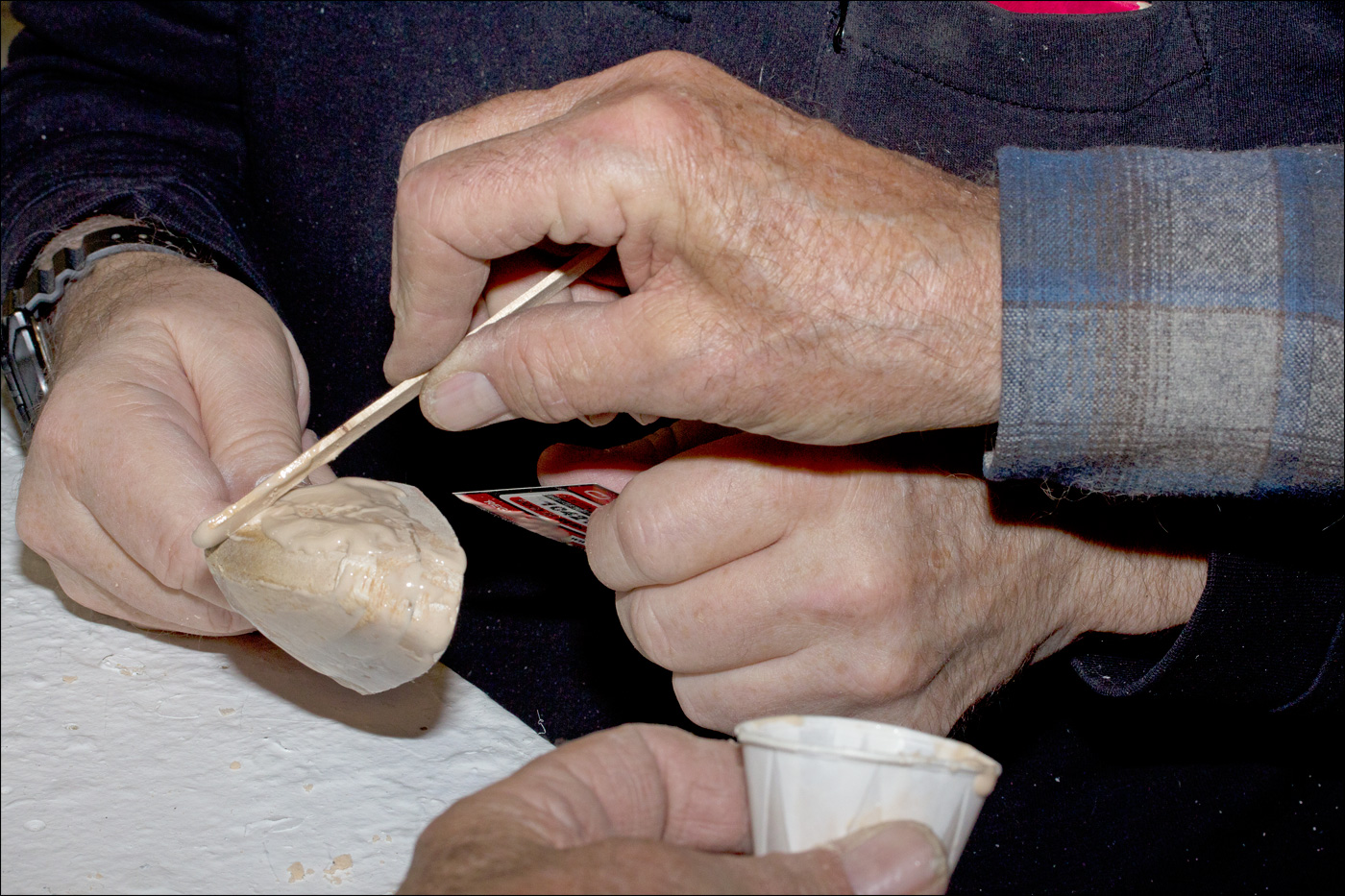
Paul mixed up some epoxy with some West System filler (to thicken the epoxy). Paul and Dick applied the mixture to the mold. When sanded, the dried epoxy made a hard, smooth surface.
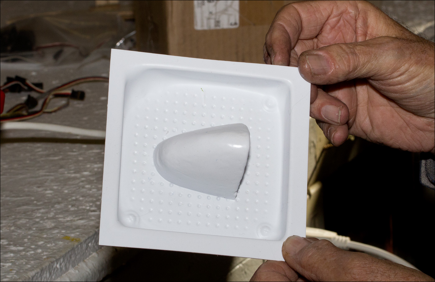
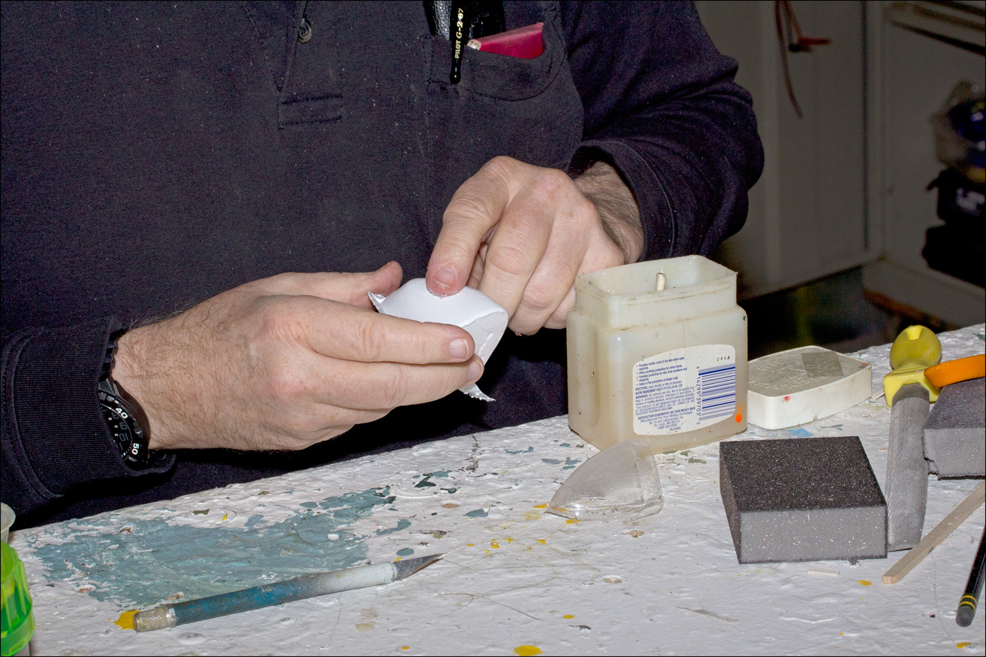
To further improve the smoothness of the mold, Paul used a white plastic material to cover the mold.
After Paul trimmed the white material around the mold, Dick used a small amount of Vaseline to, hopefully, make the newly formed lenses release more easily from the mold.
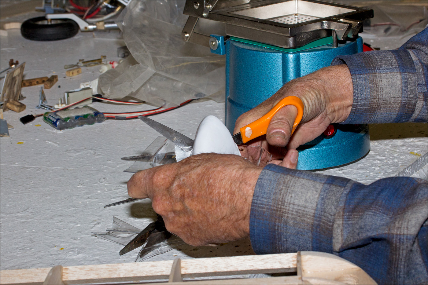
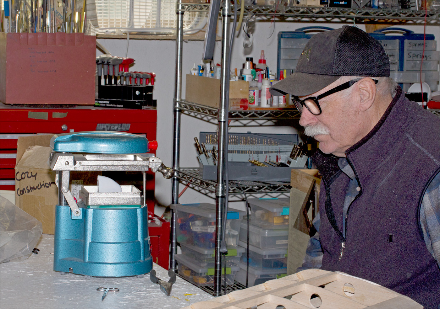
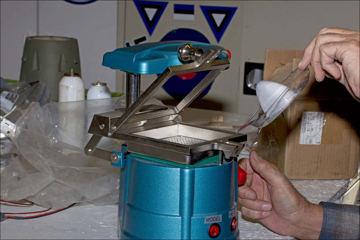
Paul created the transparent lens using the newly covered mold.
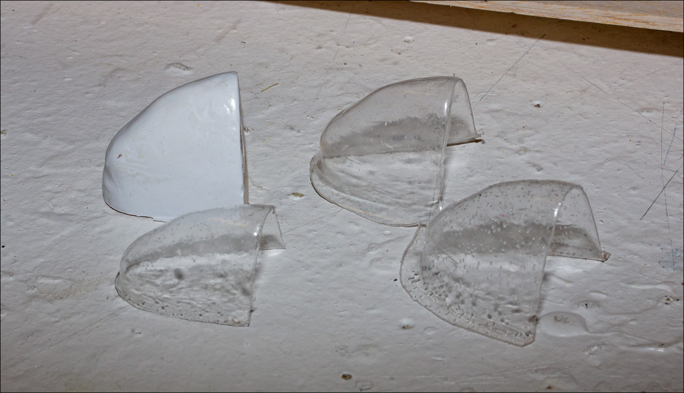
Although the lenses contained small "bubbles," I felt they would serve nicely for my wing-tip lenses. Paul made three lenses for me and I kept the mold for future use.
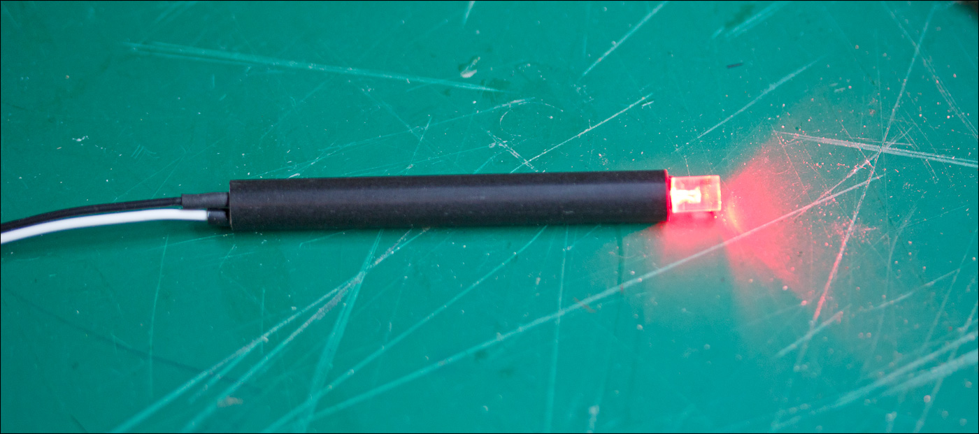
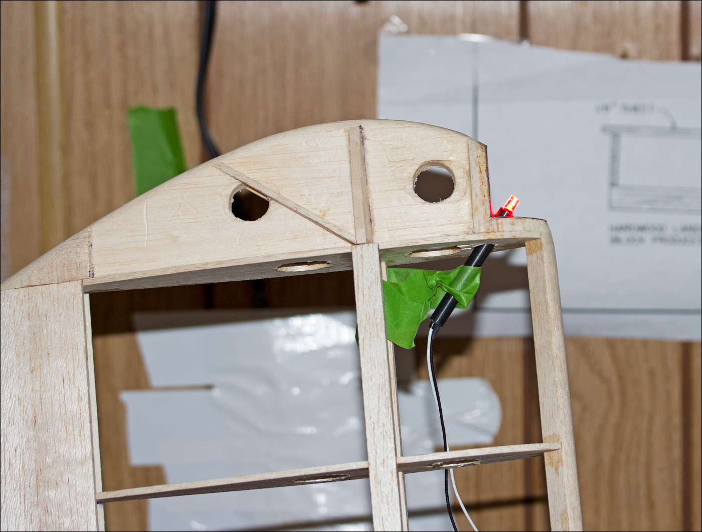
Back at my workbench,I created a LED-mount assembly. After soldering the LED connections and using heat-shrink tube to insulate the connections, I inserted the LED into a piece of arrow shaft (previously purchased from Dave Brown). The LED is held snugly in the shaft by using multiple layers of heat-shrink tubing.
I layered thin pieces of plywood inside the wing notch to provide a smooth surface and covered the plywood with stick-on HVAC tape in order to reflect as much of the LED light as possible. Paul suggested using the tape and supplied me with some. After drilling a mounting hole in the wing notch, I temporarily installed the LED assembly and connected the assembly to the controller.
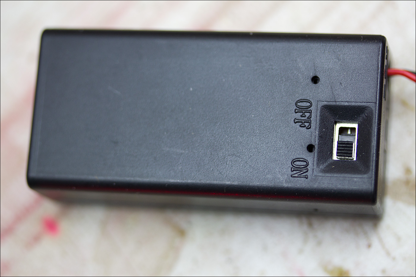
The controller is connected to a 9 V battery. The battery is contained in a battery box that has an on/off switch.
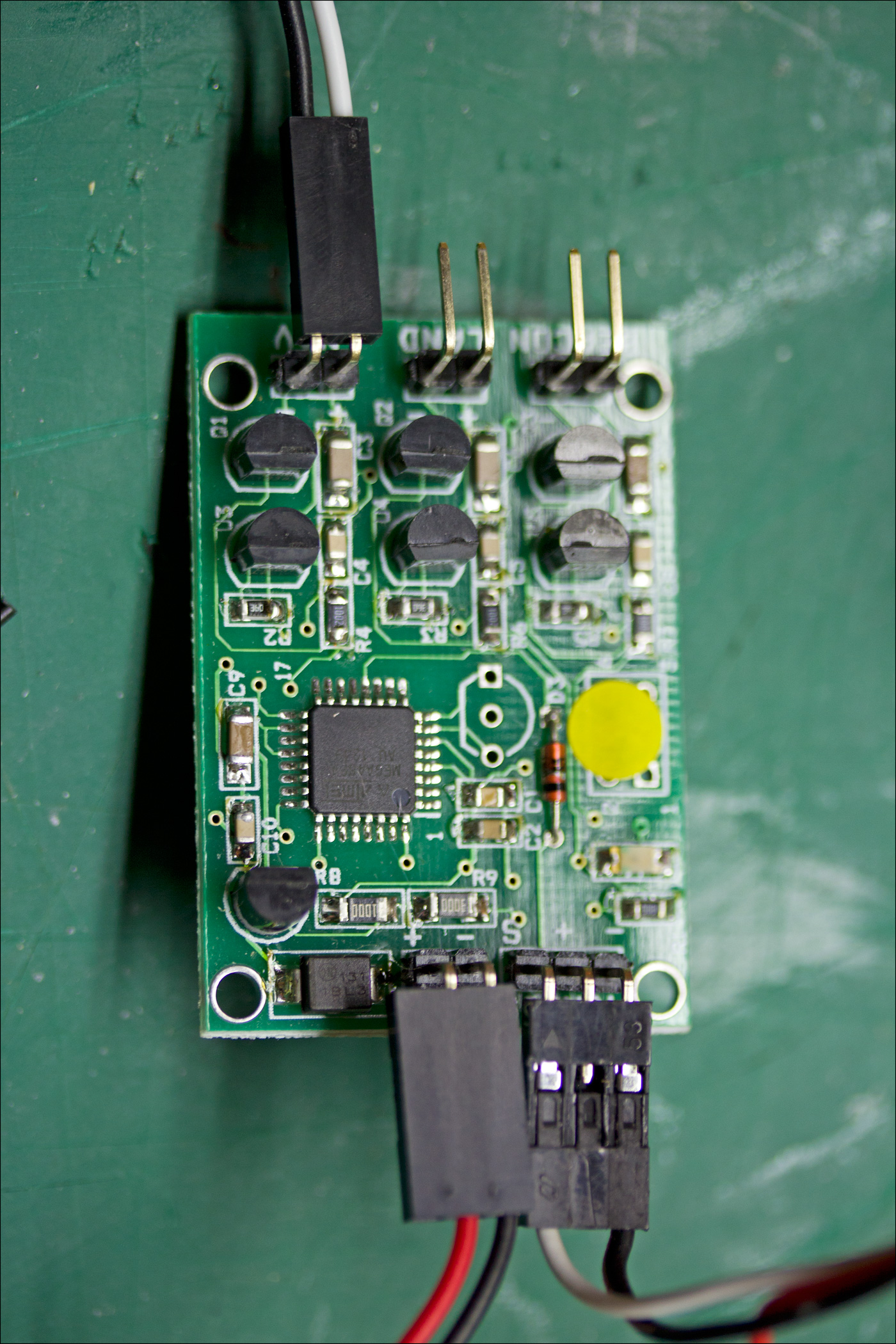
I connected the controller to the gear channel of the receiver. I disconnected the 5 V power lead from the receiver as it is not needed at the controller. I assigned the gear channel to a two-position switch on the transmitter for light control: move the switch once to activate the position lights, again for beacon lights, again for landing lights, and a fourth time to turn the lights off.
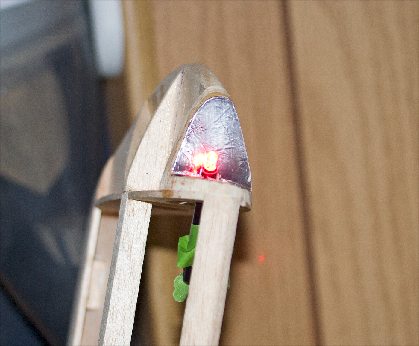
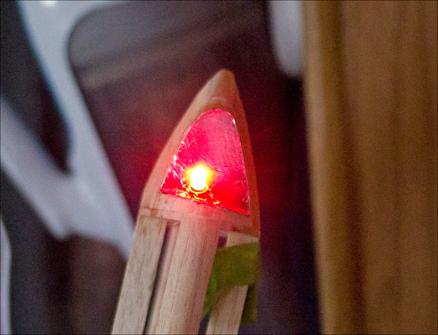
Finally, I temporarily attached one of the lenses to the wing notch. I turned off the room lights, and although it was still day time, the new led installation looked pretty neat.
Resources
- Micro Mark -- Vacuum forming machine and many other hobby tools.
About the Images
The images were taken with a Canon Rebel T3i. I used a Canon EFS 60mm f/2.8 MACRO USM. All images received simple processing in Photoshop and were saved as low-resolution JPEG images that were optimized for the Web.