Telemaster Madness
Converting a Telemaster Electro V2 ARF into a—TeleDuck
For some time, I have been a member of the local float club but have not had a float-equipped plane to fly. Not long ago, I purchased a Telemaster Electro V2 ARF from Hobby Lobby and began the project of converting it to a float-ready version—a TeleDuck. The project began before Hobby Lobby released their new Deluxe Telemaster 40 ALL Laser Cut Kit, which has provisions for floats and other features I decided to build into the Electro V2 ARF. The project breaks down into the following major sections:
- Selecting and Testing a New Power System,
- Installing the motor,
- Modifying the wing and fuselage for a bolt-on attachment,
- Building a rear strong point for the floats, and
- Constructing a removable ventral fin.
1. Selecting a New Power System
After discussing the project with club member Richard (Dick) Robb, an Alaska float-flying veteran with many years of experience, and also Jason Cole from Hobby Lobby, I decided to use the following components for the power system:
- eRC .46 Size Brushless Outrunner, 600Kv motor,
- eRC 65A Brushless Programmable ESC w/SBEC,
- POWERWING 4-Cell 14.8V 4500mAh 20C LiPo Pack,
- E-flite EC3 Device Connectors, and
- 13X8 prop.
The eRC .46 motor should have plenty of power for the 38" floats I plan to use. An inexpensive eRC Electronic Programmer completed my power system purchases: the programmer makes checking or configuring the ESC settings easy.
Before installing the motor, and after soldering the battery connectors to the ESC and LIPO, I mounted the motor and components to a simple test stand, along with the radio receiver. After hooking everything up and binding my transmitter to the receiver, I slowly increased the throttle. Nothing happened! I then read the instructions for the ESC, especially the section, "POWERING UP THE ESC FOR THE FIRST TIME & SETTING THE AUTOMATIC THROTTLE CALIBRATION." After following the instructions—everything worked as expected. Whew!
2. Installing the Motor
Due to the increased diameter of the eRC .46, the blind nuts pre-installed in the firewall for the stock AXI Gold 2826/12 Outrunner Motor were not usable for the eRC mounting plate. In order to remove the blind nuts, I cut away the balsa cover over the plywood motor mount. A hot knife helped with this as it easily cut through the adhesive holding the balsa to the fuselage. I then removed the blind nuts and filled their holes with hardwood dowels.
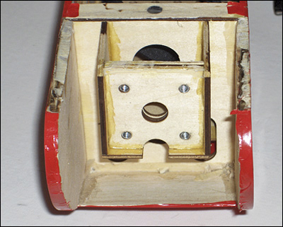
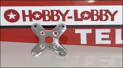
The metal mounting plate for the eRC motor is a very tight fit within the firewall space and the mounting holes are not well positioned for reusing blind nuts. Although new holes might have made the eRC motor mounting plate usable, I manufactured a custom plate. Another club member, Bob Beatty, helped me fabricate the mounting plate. After drawing a template for the plate, we cut a new plate out of a small piece of aluminum and used a drill press to accurately drill the holes. Rather than try to use blind nuts again, I used lock nuts to hold the motor to the firewall (with a drop of thread locker as extra insurance). Before the final motor installation, I painted the new motor plate flat black.
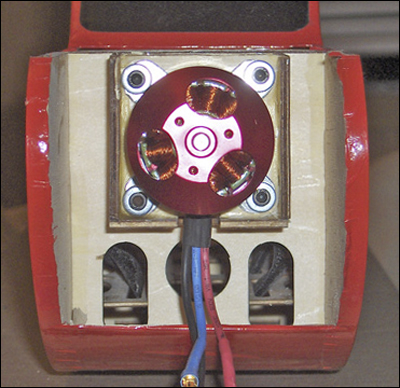
I re-glued the balsa cover over the motor mount after waterproofing the wood inside the "cowl" with a coat of red paint. Should I have to remove the motor at a later date, I will need to cut a small access hole in the balsa cover in order to remove the lock nuts. Note: the new Deluxe Telemaster 40 kit includes a completely redesigned plywood motor mount that makes motor installation easier—and recommends the use of the eRC .46 for the kit.
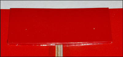
3. Bolt on Wing
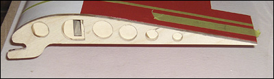
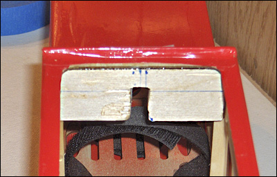
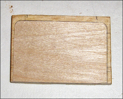
The next part of the project was to modify the wing for bolt-on attachment. To do this, I first cut a new wing-root rib out of 1/4" plywood. The rib was designed to have a lower "tongue" that slips into a corresponding slotted 1/4" plywood former epoxied to the fuselage: the tongue/slot arrangement holds the wing leading edge in place. Club member Dick Robb helped me cut out and shape the new root rib and to drill out the lightening holes: a fully equipped shop along with the skill to use the tools comes in handy for a project of this kind—thanks, Dick. I then epoxied the new root rib to one of the ARF wing halves. When the epoxy dried, I epoxied the two wing halves together. I used lots of blue tape to hold the joints together while the epoxy dried.
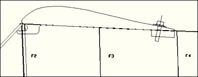
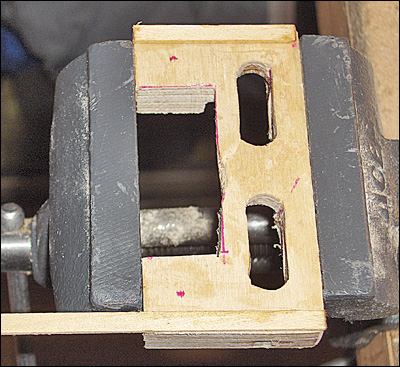
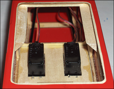
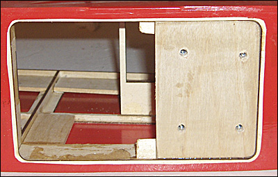
In order to hold the trailing edge of the wing in place, I first constructed a plate out of two pieces of 1/4" plywood and epoxied this to the fuselage. Portions of the pieces were cut away to lighten the assembly and to provide access to the servo mounting screws underneath the plate. I used two narrow 3/32" x 1/4" hardwood strips on the top of the plate to space the plate slightly below the top of the wing cradle: this allows the wing to fit flush in the wing cradle when the wing bolts are tightened—in spite of the wing dihedral. Before I epoxied the plate to the fuselage, I epoxied a 1/8" x 1" hardwood strip to each fuselage side and just below the top of the wing cradle. These strips not only reinforced the cradle area, but also provided additional gluing surface for the plate.
I epoxied a 1/16" plywood reinforcing plate to the top of the trailing edge where the wing bolts were to be used.
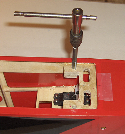
With the wing positioned onto the fuselage and securely held in place with blue tape, I drilled two holes through the reinforcing plate, the wing, and the hold-down plate. I was careful to angle the holes so that the bolt heads would snug down evenly against the reinforcing plate and conform to the slope of the wing trailing edge. I used a #7 drill for this as this is the proper size for the 1/4-20NC tap I used for the bolt holes in the mounting plate. After the mounting-plate bolt holes were tapped, I coated them with thin CA to harden the threads.
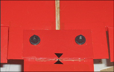
I then enlarged the holes through the wing reinforcing plate and wing so that the 1/4-20 mounting bolts would fit easily through the wing and into the threads of the hold-down plate. The bolts and root rib hold the wing securely in place for repeated—and accurate—wing positioning. Note: the new Deluxe Telemaster 40 kit provides for a bolt-on wing.
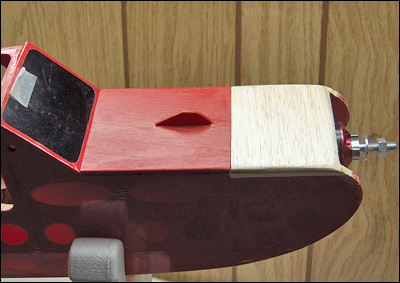
4. Rear Strong Point
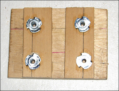
The rear strong point is located just in front of former F4 (below the wing-mounting plate). It is made out of a 1/4" piece of plywood and has blind nuts installed for the future float-attachment gear. The strong point is reinforced with 1/2" triangle stock epoxied to the underside of the plywood and to the fuselage side. A thin piece of plywood was glued to the top of the strong point so that it would fit flush with the bottom of the fuselage. Also, strips cut from 1/8" x 1" hardwood were used to reinforce the fuselage side and also to provide additional thickness for the blind nuts. Note: the new Deluxe Telemaster 40 kit includes an optional float strong point.
5. Ventral Fin
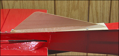
The ventral fin was constructed so that its area is approximately 15% of the total vertical stabilizer/rudder area. The fin, made out of 1/32" plywood, is mounted between two lengths of 1/4" triangle stock. The triangle stock and fin are glued to a 1/32" plate with CA. The entire assembly is very light and will be held to the bottom of the fuselage with three small screws. Note: the new Deluxe Telemaster 40 kit does not include a ventral fin on the fuselage: a fin is attached to the top of each of the floats that Hobby Lobby has announced for the kit.
Flight Testing the Land Version
After adding some new trim, radio setup, and a ground check, the land version of the Teleduck was first flown on 9/6/2012. I had to add 4.5 oz of weight in the nose to achieve balance: I balanced at 4-1/8" from the leading edge. Since I had to do a bit of rebuilding and reinforcing during the installation of the tail feathers, including prebuilding for the fin, along with the other additions behind the CG, having to add nose weight was not unexpected. The flying weight of the modified Telemaster is 106.6 oz. Floats will add, perhaps, another two pounds.
As a newbie trainee, and after flying other trainers, I ended my first training sessions with the Telemaster thinking, "This should have been my first trainer." The telemaster flies predictably and I was totally satisfied with its gentle flying characteristics. My trainer demonstrated its ability to perform basic acrobatics—even flying inverted. The Telemaster is a great choice for the wannabe pilot.
After several training flights, I had my first "Oops" with the Telemaster. After a good landing approach and just before touchdown, a gust of wind got under the wing causing a crash. The crash pushed the entire engine mount through the original—flimsey—firewall. Other damage was minimal. I quickly repaired the damage by installing a new 1/4" plywood firewall. As an additional modification, I installed blind nuts on the rear of the motor mount so that the entire motor assembly can now be secured to the firewall using four bolts, thus making future work on the motor assembly much easier: the motor, motor mount, and ESC can be removed as a unit after unbolting the four bolts from the rear of the firewall. After completing the repairs, the plane balanced perfectly without the previously used lead weight.